Plastic part design

Shrink rates for plastic parts vary depending on the materials used and the uniformity of wall thickness.
Why does injection molded material need uniform wall thickness? Without it, production could be negatively affected by large pressure drops during fill and significant variation in shrink rates. Internal stresses may subsequently appear within the injection-molded parts, causing warpage or similar defects.
For instance, thicker areas within the part can act as “runners” that alter the way the plastic fills the tool. Molten plastic prefers to follow the easiest path, so its flow will always favor the thicker wall section first. As a result, molten material may race ahead in some locations, and then “backfill” the remaining space. This can be troublesome, especially if there's not adequate venting in these areas to allow the escape of any trapped air.
When gating an injection-molded part, it is important to gate into the thickest section and then flow into thinner areas to ensure proper part pack out after filling. The flow path must remain open so the plastic continues to flow into the part details during the cooling phase.
Gating into a thin wall, or flowing through a thin area to get material to a thicker area, may create flow irregularities. The thinner area may freeze and solidify, ultimately preventing material from reaching the thick section of the part in the pack phase. This under-packing can cause higher shrinkage, potentially leading to part sink and/or warp.
Deviations in injection molding uniform wall thickness can also impact cooling rates. Thicker areas take longer to solidify, so the part must remain in the tool until sufficiently cooled for ejection. Although this isn't exactly a quality issue, cooling rates extend the cycle time which can create production inefficiencies.
Non-uniform wall thickness can also impact shear stress in the flowing plastic. At a constant fill rate, thin areas force the flow to move faster, increasing shear stress and the potential for part warpage. This same shear stress also aligns fiber reinforcements. Fibers are much stiffer in the direction of flow as compared to being perpendicular to the flow, and variable stiffness can also lead to warp.
The impact of non-uniform wall thickness may be most evident in the appearance of injection-molded parts. Variations can result in undesirable sink and cosmetic issues like flow lines. It can also be difficult for the plastic to adequately fill the tool cavity, which could interfere with proper cooling and transfer of part surface texture or gloss.
Most injection molding wall thickness issues arise during original part design, especially those of smaller, complex, multi-functional parts. For example, there may be insufficient space for a mating component in the assembly, so the plastic wall gets thinned out. This solves the design issue, but makes it more difficult to mold the part.
Designers are typically aware of these potential molding difficulties, but the fact remains that sometimes non-uniform wall thicknesses are required for proper part functionality. Therefore, designers expect the injection molder to make it happen.
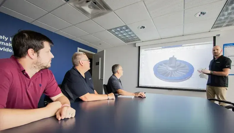
Including injection molding engineers skilled in Design for Manufacturability (DfM) analysis is essential in the initial design phase. Applying DfM principles provides insights into potential wall thickness variations and guides needed design modifications.
Our engineers view their DfM expertise as integral to serving industries that demand precision, quality, and performance from injection-molded parts. Doing so requires understanding and deploying specific DfM methodologies:
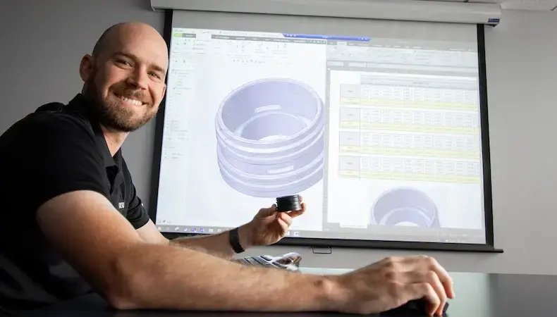
Software simulation of how plastics fill a tool provides accurate and actionable data:
In conjunction with a thorough drawing review to determine feasibility for manufacturing, software-driven part analysis identifies:
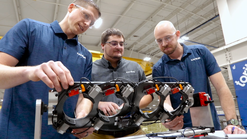
Our engineers are proven DfM experts who are committed to what Senior Project Engineer Paul Van Grinsven describes as “really understanding our customers’ parts and the intention of the parts.” DfM ensures our customers get the best possible product for the lowest possible price.


In many complex industries, decisions about which injection molder to use for cust…
READ MORE

Technologies, product needs, and customer expectations are rapidly advancing. OEMs…
READ MORE

There’s no one indicator that points to a custom injection molder’s readiness and …
READ MORE